I have built 5 previous versions of LED assemblies and several controller versions.
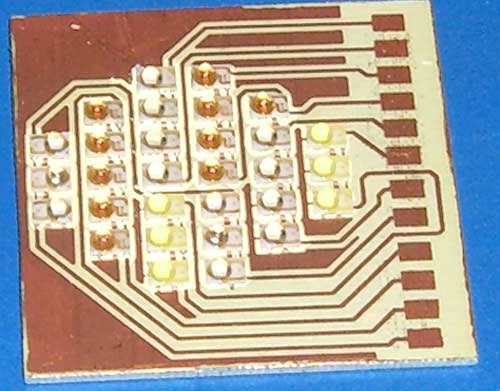
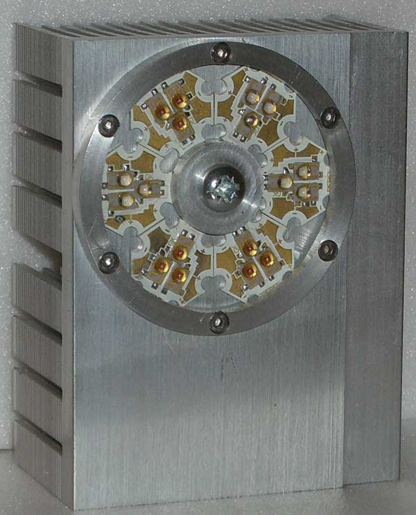
30 LED system built onto MCPCB material...my first go at using this metal-backed PCB product! The Rebels sit well within a circle diameter of 35mm:
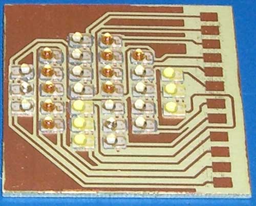
some shots of the "production" process:
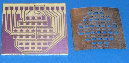
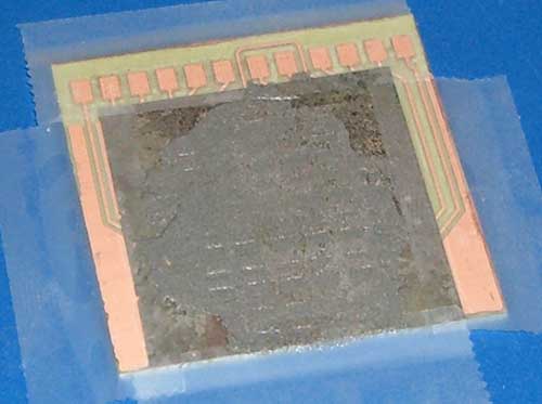
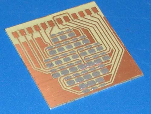
LEDs applied with tweezers, they self align when flow-soldered. I did this by placing the assembly on an upturned domestic iron:
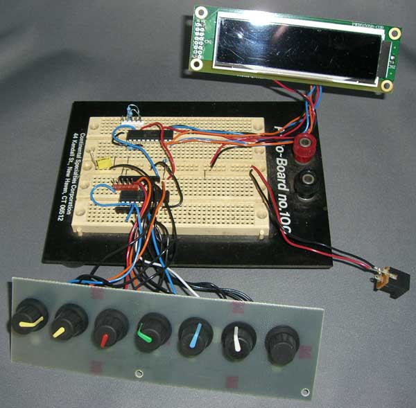
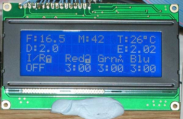
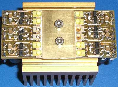
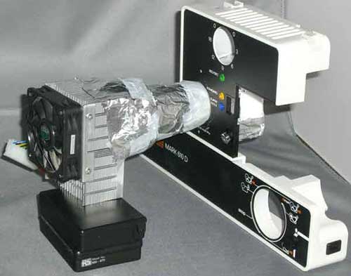
The Mk2 control system:
Mk4 and Mk3 systems. These were similar and based on commercial "Star" bases made from MCPCB, each able to take 3 Rebel LEDs:
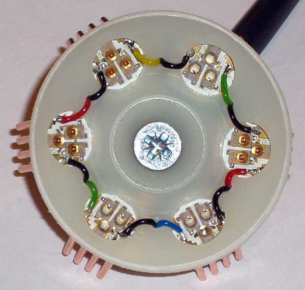
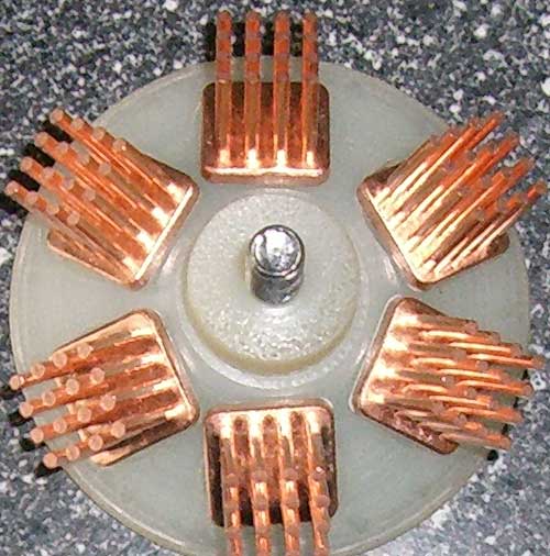
These heatsinks looked good but didn't perform well:
An even earlier version:
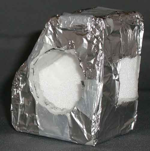
A crude light mixing assembly for the Mk4 built into the Eumig 610D:
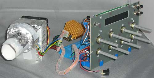
The Mk1 control system:
Introduction, how the Eumig Mark 610 D works
I chose the Eumig 610D as it is from a respected quality manufacturer, dual standard and readily available. Unfortunately, I had no idea how it worked before purchase and if I had of done, would likely have chosen something much simpler to work with!
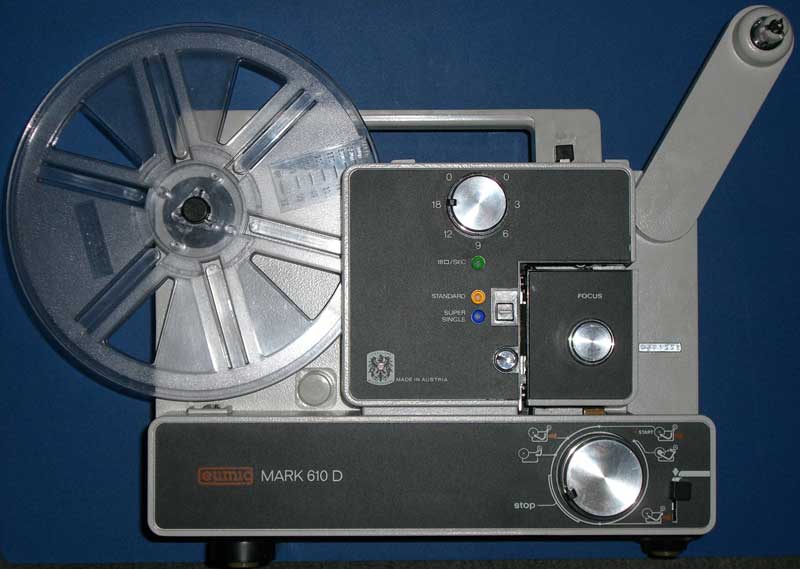
The 610D has speeds of 0, 3, 6, 9, 12 & 18fps. How it achieves these speeds is rather interesting. The motor is a mains locked synchronous affair with a different pulley choice for 50/60Hz options. Other than in the off position, the motor runs all the time, in
the same direction and at the same speed. Pulley gearing is such that the 3 bladed shutter always rotates at 1080rpm. The dual
claw pulldown is directly coupled to the shutter drive and hence always runs at 18fps.
Although the claw continues to move up and down at 18fps, for the slow motion modes, a cam mechanism effectively stops the claw from
moving into the film sprocket hole when a pulldown is not required. For example, to get 9fps, the pulldown claw is held back
every other full rotation of the shutter blade. This allows for flicker free slow motion speeds, because the bulb flicker rate is always
held at 54Hz regardless of film advance rate.
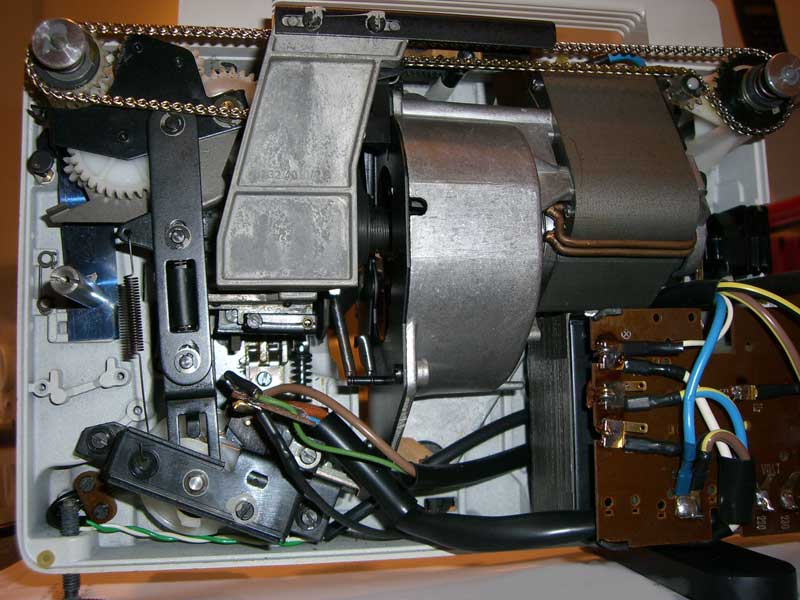
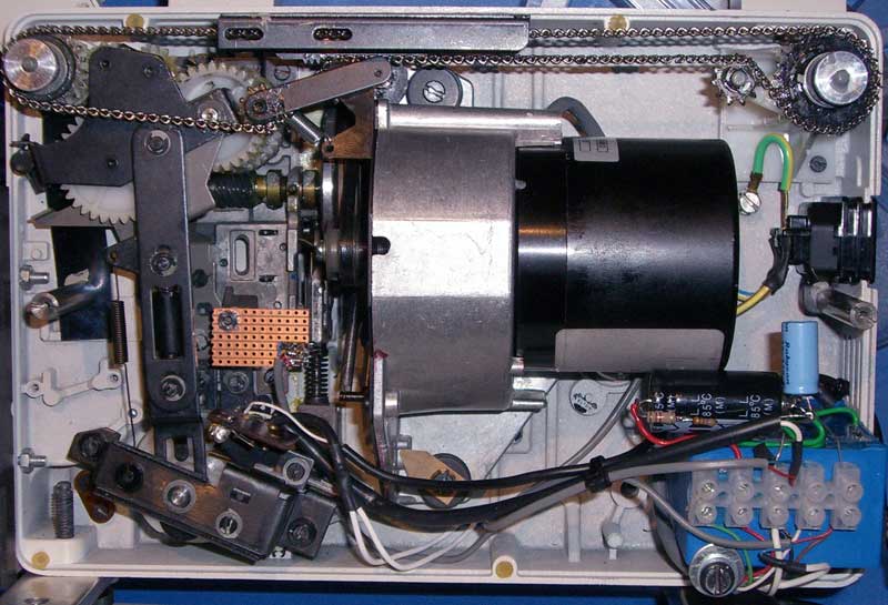
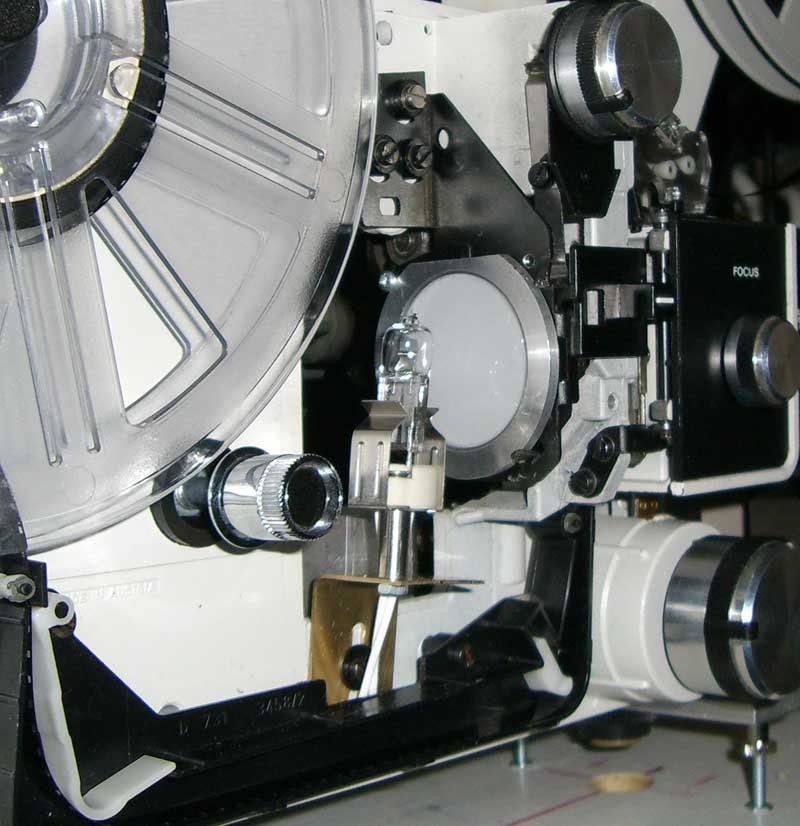
Here's an internal shot of the projector in original state. The flat plate cast piece to the left of centre is the speed actuator arm which transfers rotary motion of the speed selector knob at the top to linear sideways motion, which in turn rotates the cam, hidden behind the arm, to one of 7 positions (0,3,6,9,12,18,0):
This picture shows the key parts for frame advance control:
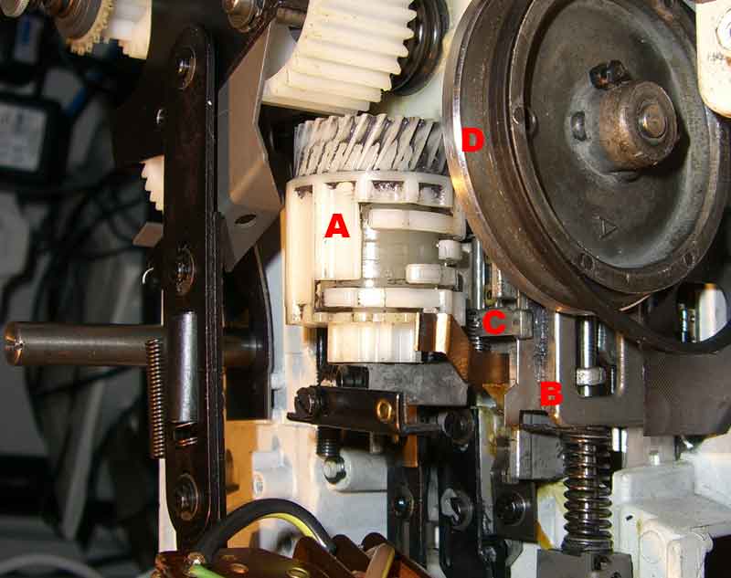
The cam A body is rotated via the cog at the bottom when a speed is selected, this includes the four cam followers (the bits that look
like different fingers). The inhibitor arm C is hinged and has a long piece under the cam unit which, when pushed down by one of the cam
fingers, stops the inhibiting arm from blocking the claw frame B from moving (towards the camera in this shot) when a pulldown is not
required. The internal drum of the cam assembly rotates at 1/6 the shutter blade rpm via the worm drive cog at the top. The cam
followers go in and out at different counts per rotation of the inner drum (cam) and depending on the rotated position of the outer
body, only one of the followers will push down on hinged arm C.
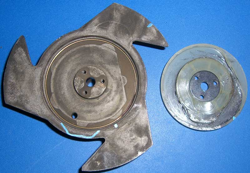
D is the 3 bladed shutter after I'd machined off the three blades...so now a non-bladed shutter ;)
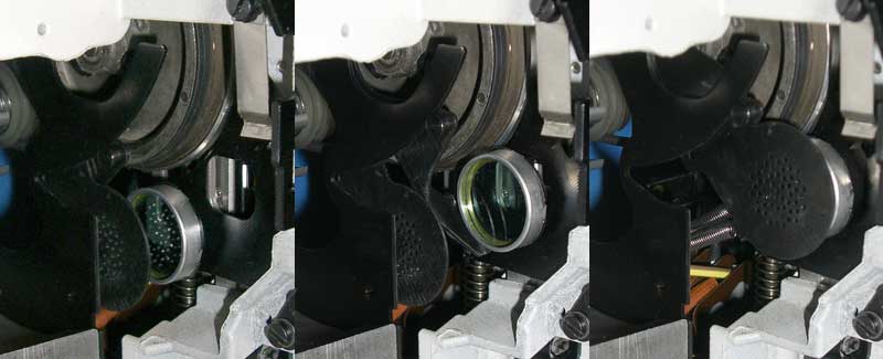
Another interesting observation is the way bulb heat and intensity is dealt with. The speed control knob also drives two swinging levers, one with a glass heat absorber and the other with a metal disc with small holes in it. The heat absorber is swung into place between the bulb and the gate for all speeds except 18fps and the light dimming disc is also swung into place in the 0fps positions. Think I will always keep the heat glass in place (unless I find a good reason not to) and will also keep the light dimming option available.
Modifying the frame pulldown/shutter assembly
To get at the blade, I had to remove the whole assembly, shown here from the claw side:
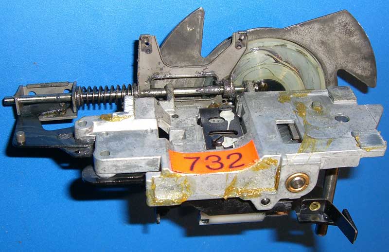
Looking at the previous and next pictures, it can also be seen how the claw vertical motion is reversed, given that the motor and the shutter/cam always rotate in the same direction! The claw frame both pivots on the spindle and slides up and down on it. Controlled by the Forward/Reverse position knob, the spring is either in compression for forward or in tension for reverse. This is achieved by sliding the spring frame on the end of the spindle (far left in the picture) up and down the spindle. This causes the cam follower on the claw frame to either ride around on the inner surface of the slot shown in the cam photo below, or against the outer surface. Looking carefully, it can be seen that the inner and outer edges of the circular slot have a mirror profile set at a rotated angle to each other. It can't be seen in these pictures, but there is also another tiny spring which moves "over-centre" at one end (a bit like your stretched out finger moves when you waggle it) to assist in keeping the up/down cam follower pressing on the correct cam edge.
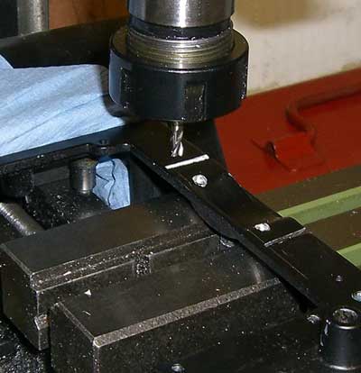
Opening out the gate
Moving on to the gate, I took advantage of the R8/S8 moveable frame to minimise the work required here. The frame sits about 1mm behind the film, so I figured it would be ok to remove it completely. All I then had to do was widen the gate along where the film edges run. The inset shows the moveable frame having been moved...right out of the projector!
The modified gate mechanism fitted back in place:
Changing out the motor
Now for the hard bit! Although the preset speeds the 610D came with would probably have been adequate, actually determining which
speed it is running at would have needed some way of detecting when the claw was being inhibited from doing a pulldown. This
seemed rather difficult as my preference for accurately triggering my machine camera is to use an optical switch and I couldn't
see how to do it on this particular machine.
My idea was to fix the cam in the 18fps mode and to replace the constant speed motor with a variable speed brushless DC motor I'd previously bought for my first projector modification. This solution turned out to be not so easy as it sounds (and also not necessary, see Triggering section)...as the motor support bracket was actually part of the motor and also held some other bits...like the chain tensioner. The motor pulley assembly was also interesting as it was spring coupled, I think to smooth out the start up...or some other reason I haven't figured out yet! Anyway, I just decided to use the same on my new motor, but found out afterwards that it doesn't work when the motor is turning slowly, so I locked up the pulley drive in the end.
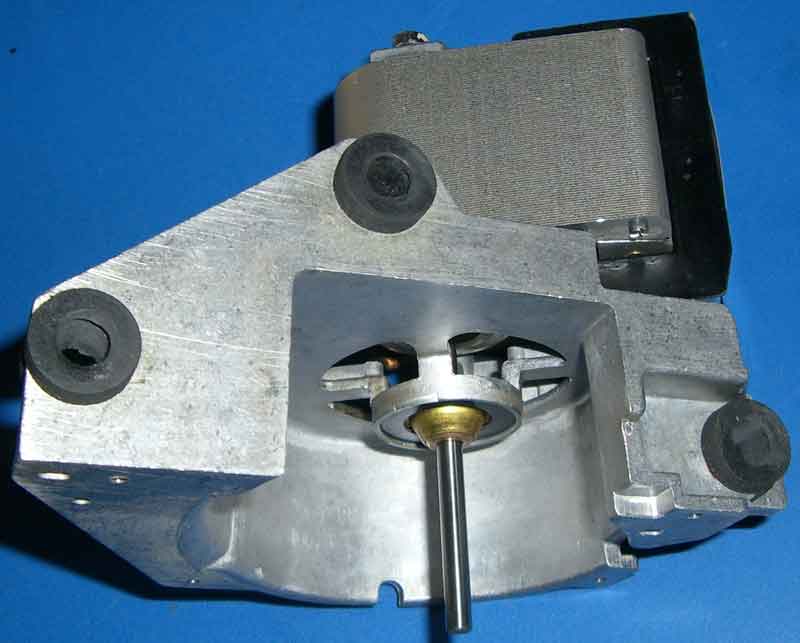
Here's the original motor with the fan and pulley assembly removed:
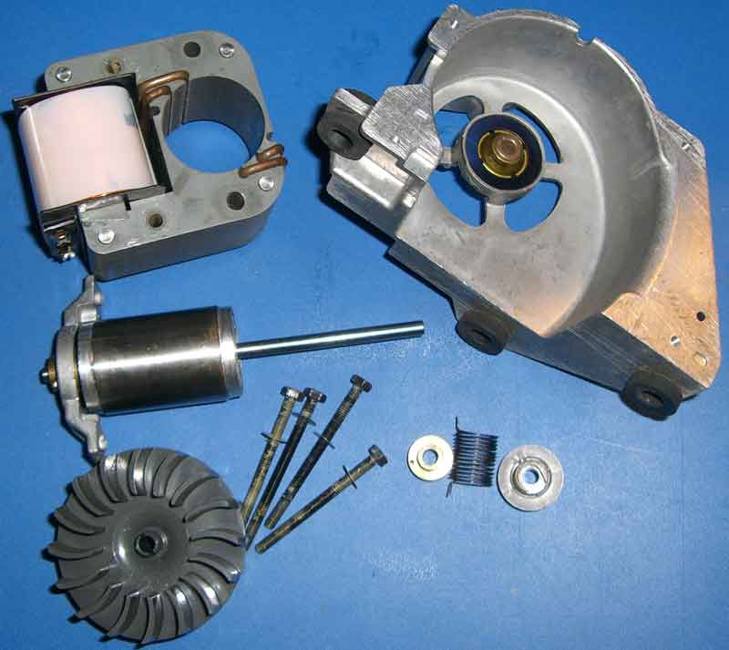
Here it is in bits:
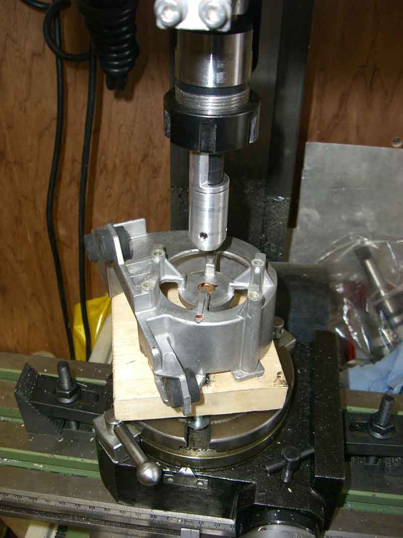
I kept the motor front/mounting die cast frame and mounted my new motor to it. This required extensive machining out, here's a shot during jigging up on the milling machine with a laser alignment tool to help out:
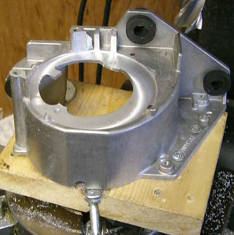
Here it is after machining out to accept the new motor:
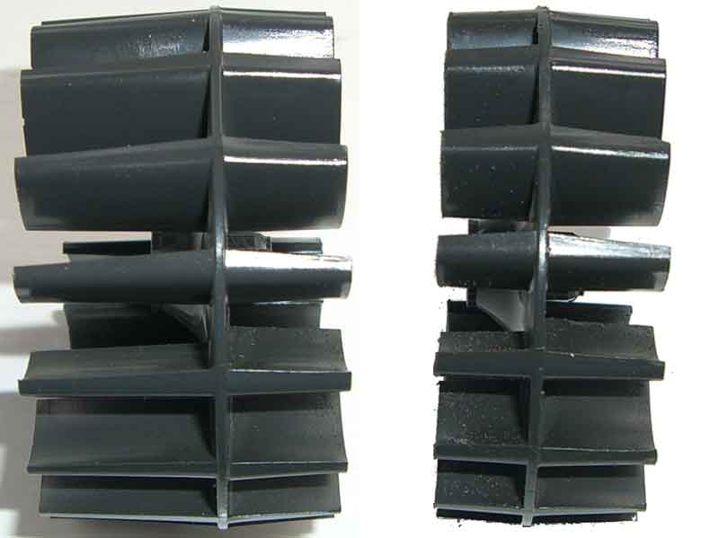
The shaft on the new motor was shorter and larger in diameter than the original motor. I needed to trim the fan a bit for the shorter shaft (it was designed to cool a 100W bulb anyway), bore out the centre and make up a shaft extender/reducer to accept the spring driven pulley. Here's the fan before and after - to trim the blades, I spun the fan in the lathe and gently offered up a Junior hacksaw as square as I could to the chuck front:
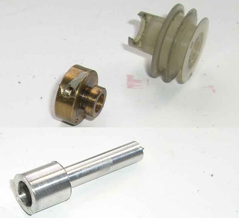
Here's the roughed-out reducer and the pulley bits (spring not shown) - I hadn't drilled and tapped for the reducer's retaining grub screws before snapping this shot:
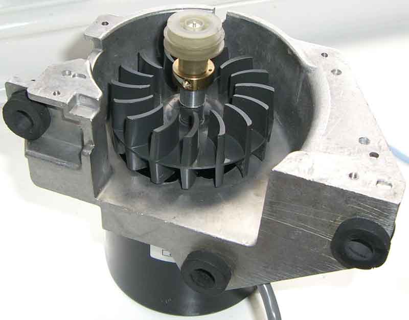
The new motor assembly - dry fit without the pulley drive spring and the end plate:
Shown here fitted. The speed actuator arm and the speed cam are now redundant and will not be refitted.
Power supply stuff
The power supply comes next. The 35W motor requires around 24V DC and the bulb requires 12V at 3A. The original transformer is no good for these new requirements and besides, it doesn't fit in the case any more due to the motor modification.
The motor supply is made from a 0-18, 0-18 mains transformer. The secondary windings are in parallel, with the output DC rectified through a bridge and smoothed with a 4700uf capacitor. The bulb circuit currently uses an external ready made 12V 5A power adaptor, similar to a computer laptop charger. I'm looking to change this to get everything inside the projector case if possible.
I also needed to generate a small amount of current (less than 20mA) at 5V for the motor speed control and the triggering circuit. This is currently derived from the +24V motor supply.
Lighting
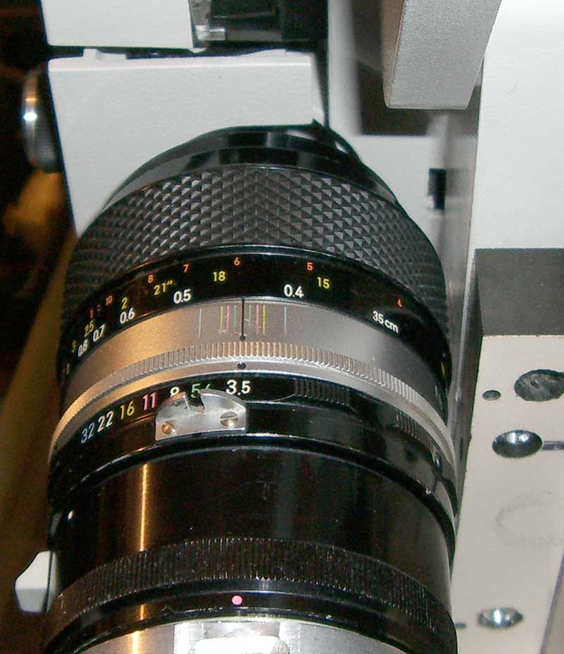
As per the modification shown here: (diy super8 telecine), I made a similar adaptation for the lamp and diffuser. I already had a 40mm diameter opal diffuser, so I had to make up an adaptor ring...a 50mm diffuser would have fitted straight in. Originally, I stuck an 80A filter and the diffuser together with a hot melt glue gun (just around the edges so I could separate them again if need be) and then glued them into the original bulb holder. I did this because I was planning to have to reverse mount the Nikon lens I'm using and it wouldn't have been so easy to fit an 80A on the lens filter ring. As it turned out, the Nikon just fitted front-in, so I went back to fitting the Opal diffuser on its own:
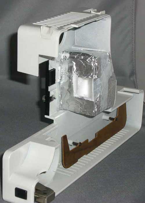
Here's a shot of the lighting and diffuser in place:
Triggering
Although it looks from the photographs like there is plenty of space around the shutter blade, in practice there isn't. I couldn't really see where to fit my optical switch sensor. So I thought I would try a Hall Effect sensor:
Experimenting with a Hall Effect sensor in the Eumig Mark 610 D
Here are the results of my experimenting with an SS443A Hall Effect sensor. These sensors are very cheap, around �1.30 and small.
The Eumig has a little bit of a strange movement to the claw mechanism - after pulldown, the claw moves out as expected, moves up one
sprocket hole's worth, moves in, then moves out again, then moves back in, finally completing the cycle with a pulldown. If
running at a lower speed than 18fps, the claw will be inhibited from moving in as appropriate (e.g. only for half the cycles for 9=fps).
This all means that the in/out movement only has to be detected but only at the end of the pulldown, else there is a danger of a double
trigger because the in/out/in movement before pulldown.
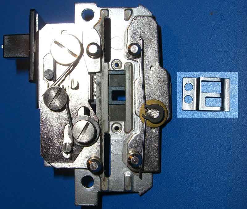
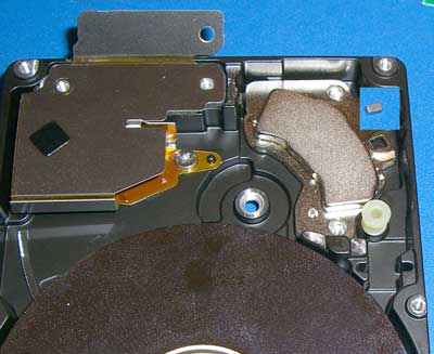
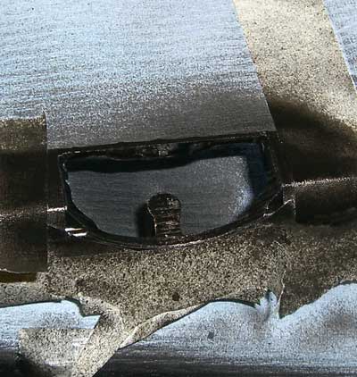
I first tried with a piece of plastic magnet, but this was not too successful. A more powerful magnet was required so knowing that hard disk drives are a great source of rare earth magnets, I stripped down an old 2GB laptop drive. The main magnet is far too powerful and large, but there is usually a small magnet to be found also. (With thanks to my friend Ian for tipping me off about this smaller one.)
The small magnet can be seen in the inset in the picture...it was inside a soft plastic sleeve and came from the square hole which can be seen below the inset:
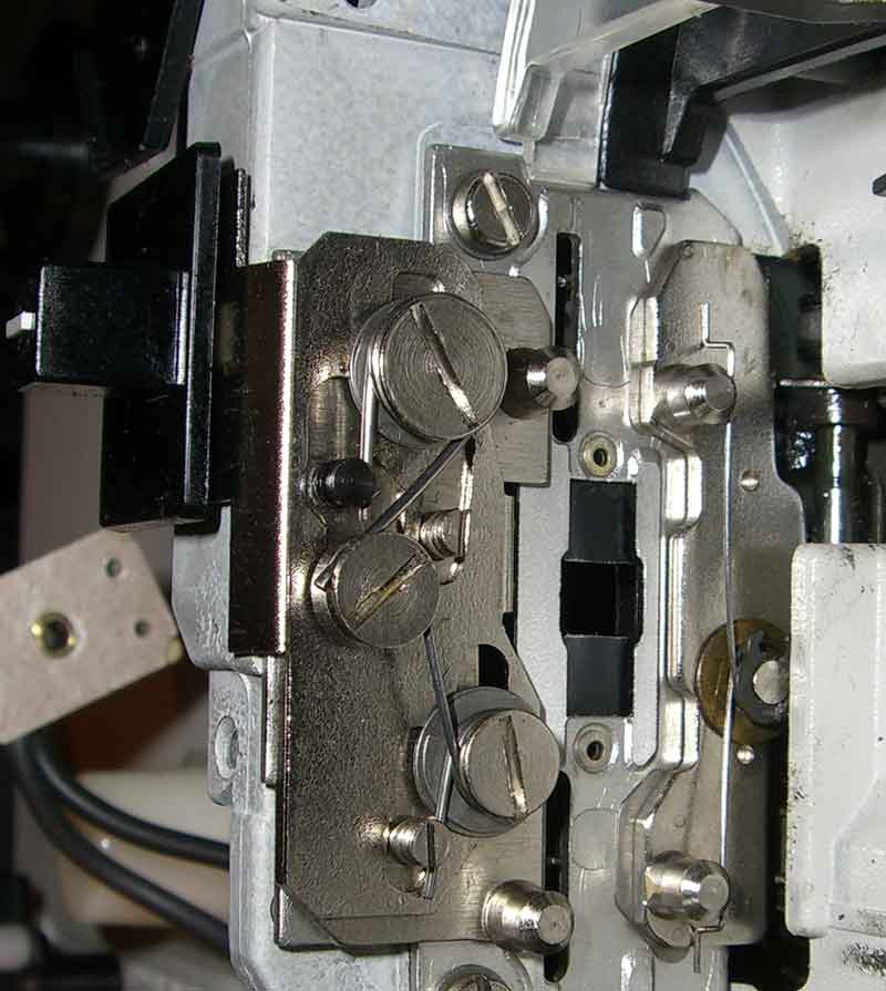
The SS443A is a unipolar device, so before fitting it, a dry run is required to see which way around the magnet needs to be to trigger the sensor. Having established this, a tiny drop of Superglue and here it is mounted:
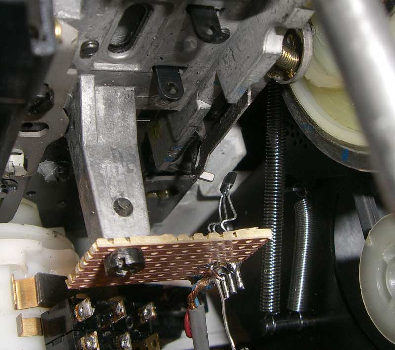
It pretty much holds itself in place, but the glue should make sure it doesn't move. Because I've fitted a variable speed motor in my Eumig, I no longer need all the cam mechanisms for speed change, so I took advantage of the mounting pillar to attach the sensor.
Here are traces of the results at different speeds (right click and Save Picture As... to get to see a larger images:
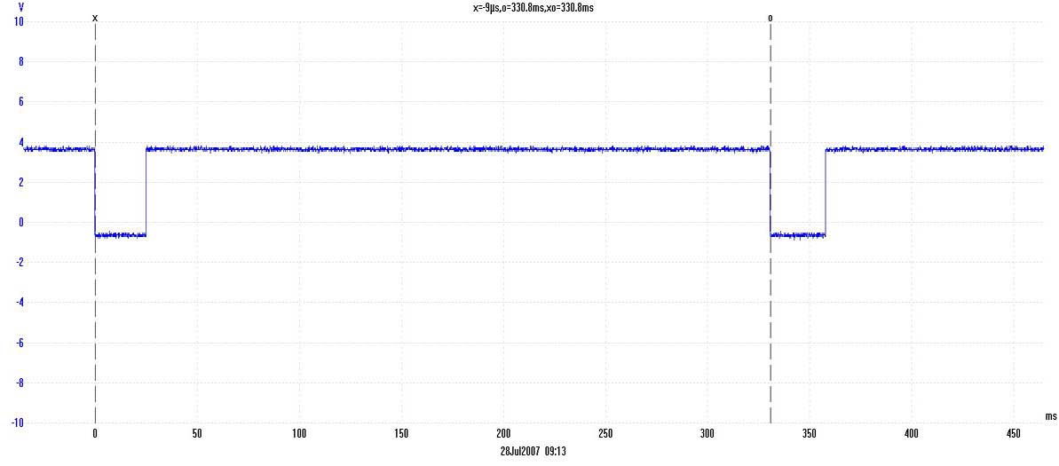
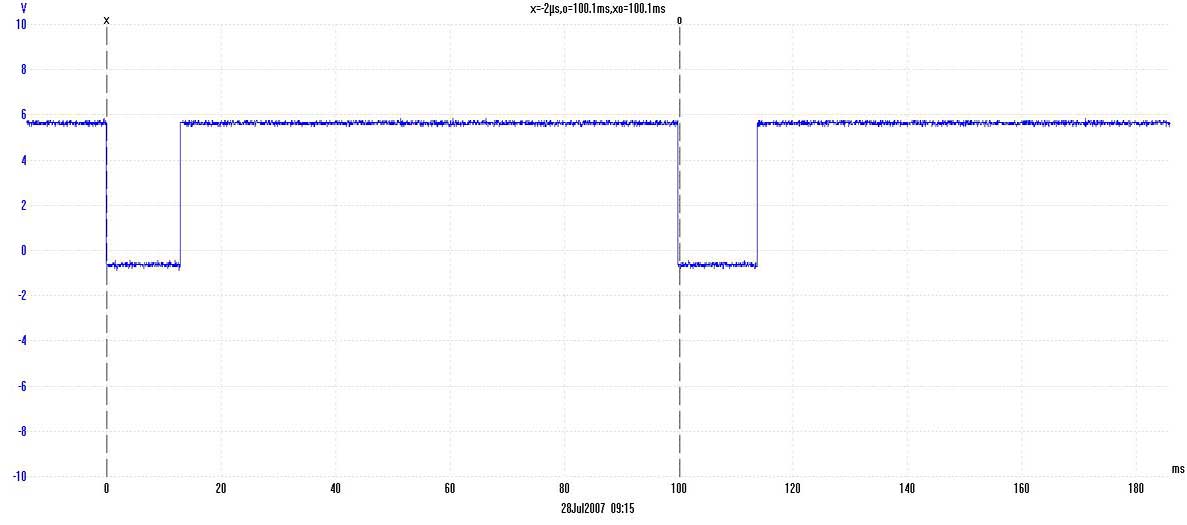
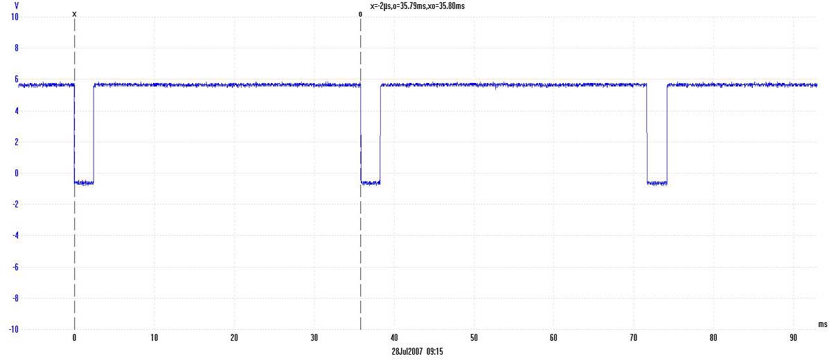
Up to around 10fps, the pulse width is probably enough to trigger a mouse directly...if that is your desire! Faster than that, a pulse stretcher will be required. In my case, the pulse is just fine as it is for my triggerable camera...although I am currently sending it via a PIC microcontroller for other development reasons.
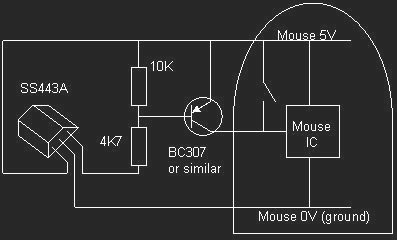
For anyone using CineCap and a mouse, an old Microsoft mouse I looked at previously had the switches between the +5V supply and the internal integrated circuit. The following circuit should work (up to around 10fps) with this type of mouse. BEWARE: This circuit is using the PC's +5V supply to the mouse for sensor power...don't short it out or you might not do your PC any good at all! Probably much better to use a stand alone regulated +5V supply for the sensor - one of those plug-top ones will do.
Post conversion thoughts
Having made the conversion, here are some thoughts from what I have learnt so far.
I was a bit hasty in changing the motor. There are some advantages:
Cutting out the front of the projector to allow the lens to get in closer
Some projector/lens combinations do not allow one to get close enough to the film plane without some drastic hacking. Here's how I dealt with the problem with my first conversion:
Before stripping down the projector, I measured the centre line of the lens (hence centre of film frame) from a reference point on the projector casing.
I also measured how far to cut in without hitting anything that matters or weakening the frame too much and decided to go in as far as the web at the back of the original lens clearance instep.
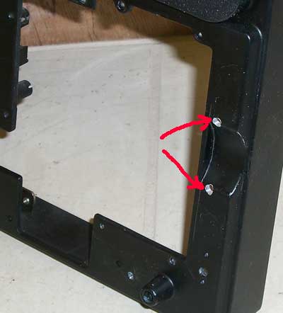
I drilled two holes as marked:
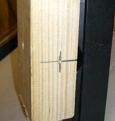
Using woodscrews from the inside of the casing, I screwed a block of wood on to the casing and mark up the lens centre point as shown:
I used a suitable sized cutter from one of those concentric rings wood cutter sets in an electric drill. The casing metal is quite soft, so cuts easily without damaging the cutter: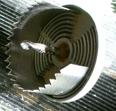
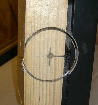
Next, I carefully cut into the required depth:
I'm fortunate enough to have a small milling machine, so I used it to cut down beside the web. Otherwise, I would have just drilled a hole in the appropriate place, passed a hacksaw blade through it and cut it out by hand:
Some black paint to tidy it up a bit:
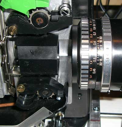
Mission accomplished! The lens shown here is a 50mm Zeiss: