Lighting
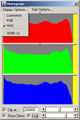 The main purpose here is to obtain the best from the limited dynamic range of CCD cameras. This means to expose each of the R, G & B channels such that the peak value from the A/D is close to maximum without clipping. This may not be the correct colour balance for the image. Corrections can be made in post processing by reducing the colour values as required.
The benefit is reduced noise rather than increased noise which could happen if the full range of a CCD pixel was not fully utilised during capture.
It is anticipated that any automatic white balance of the lighting is made on a scene by scene basis, not frame by frame.
R, G & B LEDs are used as the light source. I use Luxeon rebels and chose Royal Blue in preference to the Blue. These are a good match for the CCD Bayer filters, but do result in slightly excessive saturation. This can be reduced in post processing. I experimented with white LEDs plus red and blue, also with in-fill colours like red-amber, but there was insufficient improvement to justify the extra complication.
I use a mix of:
6 blues at 700mA
6 greens at 700mA
12 reds at 350mA
These are arranged in an approximately 4:3 rectangular ring, with the LED sequence being RGRB RGRB RGRB RGRB etc
This results in a very bright and well mixed light array which allows for heavy diffusion and can therefore be used as a soft backlight without the need for using a bounce card. Eliminates the problem of an uneven illumination across the frame which a bounce card usually produces.
The LEDs are switched on only during a frame exposure and the period they are switched on for determines the colour balance of the light as the camera shutter is held open for the longest of the three channels.
The switched system of RGB has many benefits:
1) Controllable colour balance with automatic correction for temperature drift problems.
2) Much reduced heat generation in the LEDs as they are only on for 5 to 10% time.
3) Short "flash" exposures reduce effects of any mechanical system vibration.
4) No high frequency switching of current in the LEDs during the exposure, eliminates any possibility of beat patterns.
5) Possible to use a monochrome camera to achieve similar performance to a 3-CCD colour camera by sequentially taking a R, then G then B exposure and then combining in post.
6) Possible to use a second (or fourth for R>G>B) exposure of IR light for scratch and noise reduction.
7) Possible to make automatic dual exposures for HDR, e.g. first is normal, second at +3 stops. Processing for HDR has to be done in post of course.
8) Less power required from the PSU and much less heat in the current regulators (usually run cold).
Disadvantages are:
1) More complex and expensive to build than a simple bulb or white LEDs + filter.
2) Not suitable for use with rolling shutter cameras.
3) Not a pure daylight spectrum response...but neither has a CCD camera!
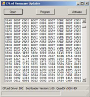
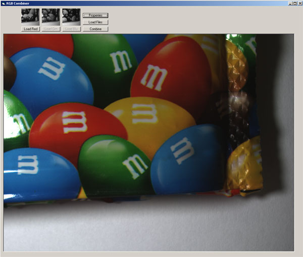 Here's a screen grab of a prototype application I made to test using a monochrome camera with the LED system operating in R>G>B sequence mode. For each trigger from the projector, three separate images are taken and save to disk in the AVI file. These are later separated using something like the SelectEvery() function in AviSynth and then combined into full colour frames. During capture, I create a simple colour preview on-the-fly from each group of three incoming frames.
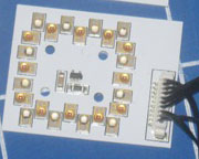
The LED circuit principle is quite simple:
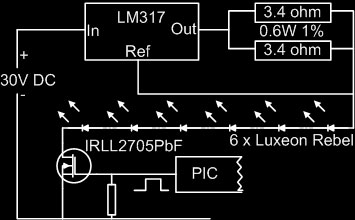
An LM317 regulator is arranged in constant current mode to supply 700mA.
The LEDs for one colour are arranged in series and switched on for the duration of the exposure.
A MOSFET is used as a switch and is driven by a precise timing pulse from a PIC16F1937 microcontroller.
There is a circuit like this for each of the three colour channels, but the red has two chains of LEDs in parallel so that each red LED runs at 350mA. This helps to reduce output level drift with short pulses and gives better light mixing.
The sequence of events is:
1) Hall Effect sensor produces a trigger from projector when a frame arrives in the gate
2) LEDs are switched on for 500us to allow the LM317s to stabilise
3) Camera trigger Mode 1 is started, to open the shutter on the camera and the RGB exposure timing begins
4) R, G & B LEDs switch off at individual times according to the required colour balance
5) Camera trigger is ended to finish the frame grab and to initiate the captured frame to be sent down the Firewire bus to the PC, where it is debayered, displayed on the monitor and added to the previous frames to create a full resolution avi file. It is also possible to save a full resolution TIF file sequence from each frame. A live histogram is also displayed and updated with each new frame which arrives.
One PIC16F1937 microcontroller is used to switch the LEDs and produce the camera trigger. Four CCP modules inside the PIC are used for very precise timing in hardware. Jitter on the timings is only 0.125us.
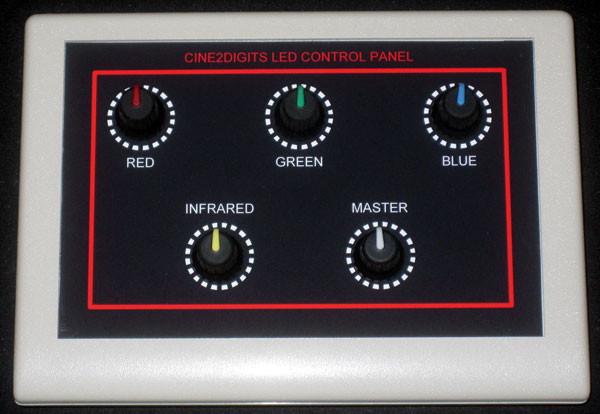
The LED switch on time is controlled by the user to obtain colour balance, or can be automatically set on a still frame at the start of a scene capture. The switch on time is also automatically adjusted for LED temperature, so exposure = user setting x temperature factor. Temperature change is slow compared with frame rates. The minimum resolution for the switch on time is 2us steps (this is not the same as the jitter of 0.125us). With exposure times around 1 to 5ms, the jitter and resolution limits are not really significant at all.
The PIC is controlled from the host PC via a USB interface. All calculations are done on the host and loaded into the timing registers in the PIC. The PIC monitors the LED temperature sensor (MCP9802A) and another PIC (16F687) which provides 5 channels of rotary encoder switch decoding, including their integrated push buttons.
Selection of input trigger polarity and delay is possible, as is camera output trigger polarity and mode (0 or 1) and there are exposure sequence options of R+G+B together or R then G then B in sequence. Either exposure mode can be optionally followed by an IR pulse to grab frames for use with scratch and noise reduction algorithms in post.
 Motor control is also built into the PIC16F1937and the LED driver board includes a PWM driver and motor reversing relay.
The firmware in this PIC can be user updated via the USB interface and a special application I've written for this purpose.
Here are some of the systems I've built for some friends:
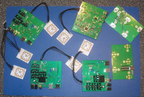
The board on the right is an optional board with hardware controls. One of those is inside this control box: