Here I collected all sorts of stuff I've engineered, designed or written along the way with this project. No particular order...I may get around to organising it one day!
Simple circuit for adjustable timing delay
Diagram explaining capture timing for a DV camcorder
Experimenting with a Hall Effect sensor in the Eumig Mark 610 D
Here are the results of my experimenting with an SS443A Hall Effect sensor. I now use one in my Mark 8 conversion and would recommend this solution over an optical one. These sensors are very cheap, around Ł1.30 and small.
The Eumig has a little bit of a strange movement to the claw mechanism - after pulldown, the claw moves out as expected, moves up one
sprocket hole's worth, moves in, then moves out again, then moves back in, finally completing the cycle with a pulldown. If
running at a lower speed than 18fps, the claw will be inhibited from moving in as appropriate (e.g. only for half the cycles for 9=fps).
This all means that the in/out movement only has to be detected but only at the end of the pulldown, else there is a danger of a double
trigger because the in/out/in movement before pulldown.
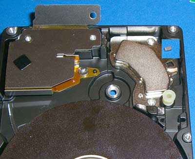
I first tried with a piece of plastic magnet, but this was not too successful. A more powerful magnet was required so knowing that hard disk drives are a great source of rare earth magnets, I stripped down an old 2GB laptop drive. The main magnet is far too powerful and large, but there is usually a small magnet to be found also. (With thanks to my friend Ian for tipping me off about this smaller one.)
The small magnet can be seen in the inset in the picture...it was inside a soft plastic sleeve and came from the square hole which can be seen below the inset:
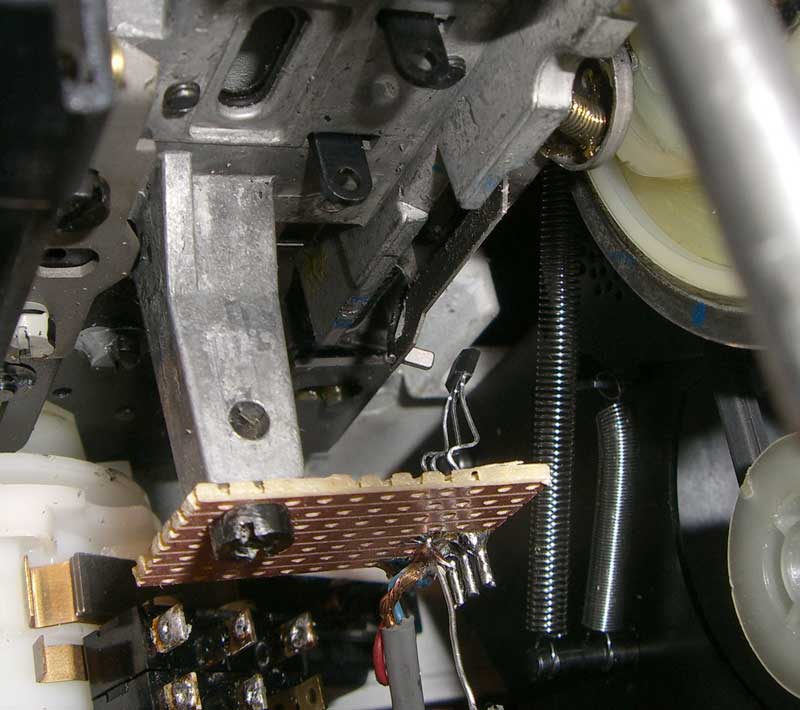
The SS443A is a unipolar device, so before fitting it, a dry run is required to see which way around the magnet needs to be to trigger the sensor. Having established this, a tiny drop of Superglue and here it is mounted.
It pretty much holds itself in place, but the glue should make sure it doesn't move. Because I've fitted a variable speed motor in the Eumig, I no longer need all the cam mechanisms for speed change, so I took advantage of the mounting pillar to attach the sensor.
Here are traces of the results at different speeds (right click and Save Picture As... to get to see a larger images):
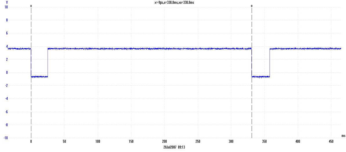
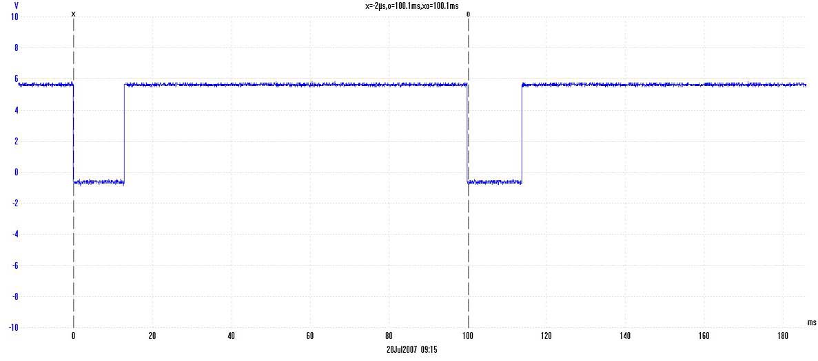
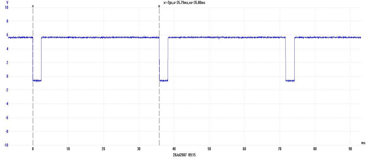
Up to around 10fps, the pulse width is probably enough to trigger a mouse directly...if that is your desire! Faster than that, a pulse stretcher will be required. In my case, the pulse is just fine as it is for my triggerable camera and goes via the LED controller.
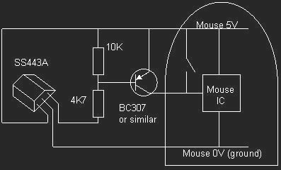
For anyone using a mouse based capture program, an old Microsoft mouse I looked at previously had the switches between the +5V supply and the internal integrated circuit. The following circuit should work (up to around 10fps) with this type of mouse. BEWARE: This circuit is using the PC's +5V supply to the mouse for sensor power...don't short it out or you might not do your PC any good at all! Probably much better to use a stand alone regulated +5V supply for the sensor - one of those plug-top ones will do.
How I think the speed change mechanism works on the Eumig Mark 610 D
The 610D has speeds of 0, 3, 6, 9, 12 & 18fps. How it achieves these speeds is rather interesting. The motor is a mains locked synchronous affair with a different pulley choice for 50/60Hz options. Other than in the off position, the motor runs all the time, in
the same direction and at the same speed. Pulley gearing is such that the 3 bladed shutter always rotates at 1080rpm. The dual
claw pulldown is directly coupled to the shutter drive and hence always runs at 18fps.
Although the claw continues to move up and down at 18fps, for the slow motion modes, a cam mechanism effectively stops the claw from
moving into the film sprocket hole when a pulldown is not required. For example, to get 9fps, the pulldown claw is held back
every other full rotation of the shutter blade. This allows for flicker free slow motion speeds, because the bulb flicker rate is always
held at 54Hz regardless of film advance rate.
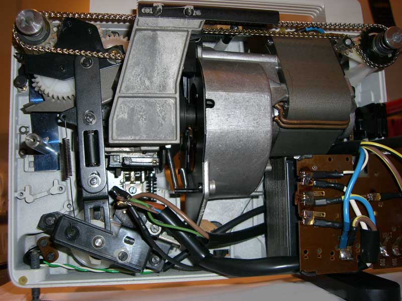
Here's an internal shot of the projector in original state. The flat plate cast piece to the left of centre is the speed actuator arm which transfers rotary motion of the speed selector knob at the top to linear sideways motion, which in turn rotates the cam, hidden behind the arm, to one of 7 positions (0,3,6,9,12,18,0):
This picture shows the key parts for frame advance control:
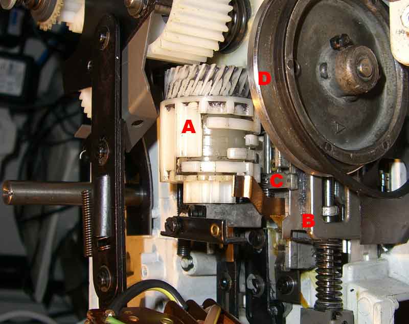
The cam A body is rotated via the cog at the bottom when a speed is selected, this includes the four cam followers (the bits that look
like different fingers). The inhibitor arm C is hinged and has a long piece under the cam unit which, when pushed down by one of the cam
fingers, stops the inhibiting arm from blocking the claw frame B from moving (towards the camera in this shot) when a pulldown is not
required. The internal drum of the cam assembly rotates at 1/6 the shutter blade rpm via the worm drive cog at the top. The cam
followers go in and out at different counts per rotation of the inner drum (cam) and depending on the rotated position of the outer
body, only one of the followers will push down on hinged arm C.
D is the 3 bladed shutter after I'd machined off the three blades...so now a non-bladed shutter ;)